This section of tutorial will explain you everything that you need to know about stepper motors. Stepper motors can be used in various areas of your microcontroller projects such as making robots, robotic arm, automatic door lock system etc. This tutorial will explain you construction of stepper motors (unipolar and bipolar stepper motors ), basic pricipal, different controlling types (Half step and Full step), Interfacing Techniques (using ULN2003) and programming your microcontroller in C to control stepper motor.
Unipolar stepper motor
The unipolar stepper motor has five or six wires and four coils (actually two coils divided by center connections on each coil). The center connections of the coils are tied together and used as the power connection. They are called unipolar steppers because power always comes in on this one pole.
Bipolar stepper motor
The bipolar stepper motor usually has four wires coming out of it. Unlike unipolar steppers, bipolar steppers have no common center connection. They have two independent sets of coils instead. You can distinguish them from unipolar steppers by measuring the resistance between the wires. You should find two pairs of wires with equal resistance. If you've got the leads of your meter connected to two wires that are not connected (i.e. not attached to the same coil), you should see infinite resistance (or no continuity).
 |
| Unipolar Stepper Motor Coils |
Working:
Stepper motors are very different from a regular DC motors. Instead of spinning like DC motors do, stepper motor steps at a specific resolution for each pulse. The motor that we are using needs 48 steps / pulses just to complete a single revolution! That should be enough to tell about its precision.
Another advantage of stepper motors is the fact that their speed of rotation can be achieved almost instantly even if you change the spinning direction.
 |
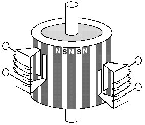
| Stepper Motor Structure |
Now lets discuss the working mechanism of a stepper motor. When we energize a coil of stepper motor, The shaft of stepper motor (which is actually a permanent magnet) align itself according to poles of energized coil. So when motor coils are energized in a particular sequence, motor shaft tend to align itself according to pole of coils and hence rotates. A small example of energizing operation is given below.
 |
| Working Principal |
We need to energize coil in a sequence. The explaination and generation of the sequence will explain in the next section of the tutorial.

No comments:
Post a Comment