Thursday, October 29, 2009

Install Windows XP Using USB Flash Drive

Removable flash memory sticks are pretty much one of the most handy little pieces of technology to come along in the last couple of years. They come in various shapes and their storage size can range from a measly 128 MB to a whopping 32 GB.

So I thought, with the speed of flash drives today, it could be possible to install Windows XP onto those PCs in a much faster time than with optical media (CD/DVD). Plus with all the motherboards I use, I always make sure that the motherboards support booting from USB as it’s a very handy feature.

Requirements:
  • A copy of Windows XP Home or XP Professional.
  • USB memory stick (2 GB recommended - 1 GB minimum)
  • A motherboard that is capable of booting from a USB drive (check your motherboard manual if not sure). Most computers have this option.
Steps :

(1) Download this zip file from any of the link below :

Link 1

(2) Extract it and open the folder : USB_MultiBoot_10
(3) Open the file : USB_MultiBoot_10.cmd


(4) Press any key to display next menu
(5) Choose the second option i.e. "H" by entering H and pressing enter. Don't close this window.


(6) A window will open. Choose File System as "NTFS" and uncheck other options. Click Start.

Note : This will completely erase all data. Backup data if necessary


(7) When the process completes, click Close. Go back to the command prompt window. We using Pen Drive as the source so we will not change the first option. Now we will give the path of Windows XP Source i.e. Windows CD Path.

NOTE : If you have the image of Windows XP, mount it on a virtual drive.

Enter "1" and press enter. In the window, select the drive having Windows XP setup. Click OK.


(8) In the dialogue box, click "Yes".


(9) Enter the Owner Full Name, Organization Name, Product Key, and other information as asked by the process. If you are unsure of any field, enter anything or use default value. In the final dialogue box, press OK.

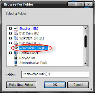
(10) Go back to command prompt. Now select the option to choose USB Drive path by entering "2" and pressing enter.


(11) Choose the USB Drive in the windows and press enter.


(12) Go back to command prompt. Now select the option to start the process of making bootable USB Windows XP Drive by entering "3" and pressing enter.


(13) Standby as the process completes. If any dialogue pops up, press "Yes".

(14) After the process completes, your USB drive is ready to be used for installing Windows XP.

(15) Now, insert your USB Flash Drive/Flash Disk/Thumb Drive to your system. Go to BIOS and make USB HDD (or USB ZIP in some other machine) as primary boot device. For more information on how to boot from bootable USB :http://www.techquark.com/2009/06/boot-your-computer-from-bootable-usb.html

(16) Boot from the USB.

(17) Providing it boots from the USB flash drive, you will now be shown two options. One with the words GUI and one with the words Text Mode. Choose the Text Mode option first.

(18) Now you will see what you normally would see during a CD install of XP. Just follow the on-screen instructions as always. One note is that, if you need to create a new partition for your new Windows XP installation, once the partition is fully formatted, instantly turn off the PC as the install will need to be restarted so the flash drive can recognize the layout of your partitions correctly. Follow the instructions below:
  1. Create a new partition and format it as normal
  2. Once the partition is formatted, restart your PC and when the options come up again choose Text Mode
  3. Highlight the newly formatted partition, press enter, move down to make no changes, and press enter
(19) Okay, now after that all goes through and the PC restarts, simply chose the GUI option on the menu and let the Windows XP install go along as it would normally do. I must advise that you DO NOT REMOVE the USB stick until you’re actually past the setup stage. Once you have just booted into Windows XP for the first time, you can go ahead and remove the USB stick.

(20) Congratulations! You have just installed Windows XP without the need for a CD/DVD drive.

Saturday, September 19, 2009

PIC16F84A Clock

Description:


This is a simple clock that uses PIC16F84A ucontroller,4050 CMOS, seven segment (common anode), and few other components.
Short the same pins of 7-segment (a with a, b with b and so on) and connect them with appropriate 4050 pin. Also make sure to invert D3 & D4 like this:


7-Segment CA pin out:

Schematic:


Top:


Bottom:

Components:

  • IC3 PIC61F84A
  • IC1 & IC2 Cmos 4050
  • Resistors, R1 - R3 10K ohm 0.25W
  • S1 - S2, Push Switches
  • Ceramic Capacitors,C1-C2 30pF
  • Q1 4 MHz Crystal
  • D1-D4 seven segment CA
Hex code:

:100000002A28FF3FFF3FFF3F8C00030E83018D0036
:100010000A088E008A0104088F000E28960803192A
:100020009503960B20289508031D20280130950084
:10003000E8309600483097070318960A0130980078
:100040000B110F0884000E088A000D0E83008C0E21
:100050000C0E0900FF309100FF30920001309C210E
:100060000030C9210030CB211116C821051E61289E
:10007000C030C600F930C700A430C800B030C90095
:100080009930CA009230CB008230CC00D830CD00FD
:100090008030CE009030CF00C030BC00CF30BD00EB
:1000A000A430BE008630BF008B30C0009230C1004B
:1000B0009030C200C330C3008030C4008230C5001D
:1000C00089283F30C6000630C7005B30C8004F307B
:1000D000C9006630CA006D30CB007D30CC002730BF
:1000E000CD007F30CE006F30CF003F30BC003030CD
:1000F000BD005B30BE007930BF007430C0006D3091
:10010000C1006F30C2003C30C3007F30C4007D307E
:10011000C500051EA4280130BE210030BC210130DD
:1001200095210230BE210030BC21013095210430E0
:10013000BE210030BC21013095210830BE210030A5
:10014000BC2101309521BC28FE30BE21FF30BC21EE
:1001500001309521FD30BE21FF30BC2101309521B9
:10016000FB30BE21FF30BC2101309521F730BE218C
:10017000FF30BC210130952101309500E830960018
:100180004830970098019A019B019C010C309D001A
:10019000D7218230D3218B178B16D9211808013C27
:1001A000031DE7289B0A98019A011B083C3C031D8C
:1001B000E7289B019C0A1C083C3C031DE7289C0186
:1001C0009D0A1D080D3C031DE72801309D001430D9
:1001D0001A02031C9A0A051EF0280130BE21F228DB
:1001E000FE30BE211D08093C0318F9284708BC2130
:1001F0000029051EFE28FF30BC2100290030BC214B
:100200000130A3211D08A1000A30A200DB21230830
:100210009E001E0899001908463E840000089900B7
:100220000F301A0203181C29051E1A2980301902E2
:1002300099001C2980309907051E21290230BE2112
:100240002329FD30BE211908BC210130A3211C083F
:10025000A1000A30A200E92123089F001F0899008D
:1002600019083C3E8400000899000F301A02031858
:100270004129051E3F29803019029900412980300B
:100280009907051E46290430BE214829FB30BE21AE
:100290001908BC210130A3211C08A1000A30A200CA
:1002A000DB212308A0002008990019083C3E8400A7
:1002B00000089900051E5F290830BE216129F7302A
:1002C000BE211908BC210130A321051E6A29FF3077
:1002D000BC216C290030BC21051E71290030BE21D3
:1002E0007329FF30BE211214C7219214C621061CA7
:1002F0008229061C7D29000079299C0A1C083B3CA8
:10030000031C9C01861C8F29861C882900008429D7
:100310009D0A1D080C3C03188F2901309D00921086
:10032000C6211210C721CE28942995001508A200D5
:100330006430A3003230AA2995001508A200643069
:10034000A3000A30AA29A1002108A2000A30A300B4
:100350000130AA29A400FF30A5002308A700220825
:10036000A600173025070318B229A60BB129A70B41
:10037000AF29A40BAD2908009400C0299300C3291C
:10038000140886000800130885000800CD29CD292F
:10039000D0299200CD299100D029120866000800CA
:1003A0001108650008009E001E0862000800831600
:1003B000080083120800A2080319E6292208210276
:1003C000031CE62922082102A100DE292108A3003E
:1003D0000800A401A2080319F62922082102031C1F
:1003E000F62922082102A100A40AED292408A3006D
:1003F0000800FF3FFF3FFF3FFF3FFF3FFF3FFF3F43
:10040000FF3FFF3FFF3FFF3FFF3FFF3FFF3FFF3FFC
:10041000FF3FFF3FFF3FFF3FFF3FFF3FFF3FFF3FEC
:10042000FF3FFF3FFF3FFF3FFF3FFF3FFF3FFF3FDC
:10043000FF3FFF3FFF3FFF3FFF3FFF3FFF3FFF3FCC
:10044000FF3FFF3FFF3FFF3FFF3FFF3FFF3FFF3FBC
:10045000FF3FFF3FFF3FFF3FFF3FFF3FFF3FFF3FAC
:10046000FF3FFF3FFF3FFF3FFF3FFF3FFF3FFF3F9C
:10047000FF3FFF3FFF3FFF3FFF3FFF3FFF3FFF3F8C
:10048000FF3FFF3FFF3FFF3FFF3FFF3FFF3FFF3F7C
:10049000FF3FFF3FFF3FFF3FFF3FFF3FFF3FFF3F6C
:1004A000FF3FFF3FFF3FFF3FFF3FFF3FFF3FFF3F5C
:1004B000FF3FFF3FFF3FFF3FFF3FFF3FFF3FFF3F4C
:1004C000FF3FFF3FFF3FFF3FFF3FFF3FFF3FFF3F3C
:1004D000FF3FFF3FFF3FFF3FFF3FFF3FFF3FFF3F2C
:1004E000FF3FFF3FFF3FFF3FFF3FFF3FFF3FFF3F1C
:1004F000FF3FFF3FFF3FFF3FFF3FFF3FFF3FFF3F0C
:10050000FF3FFF3FFF3FFF3FFF3FFF3FFF3FFF3FFB
:10051000FF3FFF3FFF3FFF3FFF3FFF3FFF3FFF3FEB
:10052000FF3FFF3FFF3FFF3FFF3FFF3FFF3FFF3FDB
:10053000FF3FFF3FFF3FFF3FFF3FFF3FFF3FFF3FCB
:10054000FF3FFF3FFF3FFF3FFF3FFF3FFF3FFF3FBB
:10055000FF3FFF3FFF3FFF3FFF3FFF3FFF3FFF3FAB
:10056000FF3FFF3FFF3FFF3FFF3FFF3FFF3FFF3F9B
:10057000FF3FFF3FFF3FFF3FFF3FFF3FFF3FFF3F8B
:10058000FF3FFF3FFF3FFF3FFF3FFF3FFF3FFF3F7B
:10059000FF3FFF3FFF3FFF3FFF3FFF3FFF3FFF3F6B
:1005A000FF3FFF3FFF3FFF3FFF3FFF3FFF3FFF3F5B
:1005B000FF3FFF3FFF3FFF3FFF3FFF3FFF3FFF3F4B
:1005C000FF3FFF3FFF3FFF3FFF3FFF3FFF3FFF3F3B
:1005D000FF3FFF3FFF3FFF3FFF3FFF3FFF3FFF3F2B
:1005E000FF3FFF3FFF3FFF3FFF3FFF3FFF3FFF3F1B
:1005F000FF3FFF3FFF3FFF3FFF3FFF3FFF3FFF3F0B
:10060000FF3FFF3FFF3FFF3FFF3FFF3FFF3FFF3FFA
:10061000FF3FFF3FFF3FFF3FFF3FFF3FFF3FFF3FEA
:10062000FF3FFF3FFF3FFF3FFF3FFF3FFF3FFF3FDA
:10063000FF3FFF3FFF3FFF3FFF3FFF3FFF3FFF3FCA
:10064000FF3FFF3FFF3FFF3FFF3FFF3FFF3FFF3FBA
:10065000FF3FFF3FFF3FFF3FFF3FFF3FFF3FFF3FAA
:10066000FF3FFF3FFF3FFF3FFF3FFF3FFF3FFF3F9A
:10067000FF3FFF3FFF3FFF3FFF3FFF3FFF3FFF3F8A
:10068000FF3FFF3FFF3FFF3FFF3FFF3FFF3FFF3F7A
:10069000FF3FFF3FFF3FFF3FFF3FFF3FFF3FFF3F6A
:1006A000FF3FFF3FFF3FFF3FFF3FFF3FFF3FFF3F5A
:1006B000FF3FFF3FFF3FFF3FFF3FFF3FFF3FFF3F4A
:1006C000FF3FFF3FFF3FFF3FFF3FFF3FFF3FFF3F3A
:1006D000FF3FFF3FFF3FFF3FFF3FFF3FFF3FFF3F2A
:1006E000FF3FFF3FFF3FFF3FFF3FFF3FFF3FFF3F1A
:1006F000FF3FFF3FFF3FFF3FFF3FFF3FFF3FFF3F0A
:10070000FF3FFF3FFF3FFF3FFF3FFF3FFF3FFF3FF9
:10071000FF3FFF3FFF3FFF3FFF3FFF3FFF3FFF3FE9
:10072000FF3FFF3FFF3FFF3FFF3FFF3FFF3FFF3FD9
:10073000FF3FFF3FFF3FFF3FFF3FFF3FFF3FFF3FC9
:10074000FF3FFF3FFF3FFF3FFF3FFF3FFF3FFF3FB9
:10075000FF3FFF3FFF3FFF3FFF3FFF3FFF3FFF3FA9
:10076000FF3FFF3FFF3FFF3FFF3FFF3FFF3FFF3F99
:10077000FF3FFF3FFF3FFF3FFF3FFF3FFF3FFF3F89
:10078000FF3FFF3FFF3FFF3FFF3FFF3FFF3FFF3F79
:10079000FF3FFF3FFF3FFF3FFF3FFF3FFF3FFF3F69
:1007A000FF3FFF3FFF3FFF3FFF3FFF3FFF3FFF3F59
:1007B000FF3FFF3FFF3FFF3FFF3FFF3FFF3FFF3F49
:1007C000FF3FFF3FFF3FFF3FFF3FFF3FFF3FFF3F39
:1007D000FF3FFF3FFF3FFF3FFF3FFF3FFF3FFF3F29
:1007E000FF3FFF3FFF3FFF3FFF3FFF3FFF3FFF3F19
:1007F000FF3FFF3FFF3FFF3FFF3FFF3FFF3FFF3F09
:084000000F000F000F000F007C
:02400E00F13F80
:104200007700770077002E006A006F00730065006A
:10421000700069006E006F002E0063006F002000C8
:104220002D0020004A0050003800340031002D00DD
:1042300034002E0068006500780020002A002A0063
:104240002A00200054004F00520020002A002A00BB
:104250002A0020004A0075006E0020003100330063
:104260002000320030003000350020002D002000FA
:104270004C0061007300740020007600650072003D
:00000001FF


Friday, September 11, 2009

Dual Power Supply


This schematics is of dual power supply, having voltage output 3,5,6,9,12,15 and -3,-5,-6,-9,-12,-15. LM 317 is adjustable 3-terminal positive voltage regulator and LM 337 is adjustable 3-terminal negative voltage regulator.
Switch S1 is for +ve and S2 is for -ve voltage respectively.


click on image to zoom

All diodes are 1N4007
R1, R3 270 ohm
R2 1K2 ohm
R4, R10 390 ohm
R5, R11 820 ohm
R6, R12 1K ohm
R7, R13 1K65 ohm
R8, R14 2K35 ohm
R9, R15 3K ohm
LM317T
LM337T
C5, C8 2200uF 25v electrolyte
C6, C7, C9, C10 22uF 25v electrolyte
C1-C4 0.1uF Ceramic
F1 0.5A fuse
S Switch
S1, S2 6-way rotary switch
T1 Center taped transformer 15-0-15v 220v
Red LED

Friday, September 4, 2009

Parallel Port Interfacing


A parallel port is a type of socket found on personal computers for interfacing with various peripherals. It is also known as a printer port.
PC parallel port is 25 pin, D-shaped female connector in the back of the computer. Not all 25 are needed always. Usually you can easily do with only 8 output pins (data lines) and signal ground.

The original IBM-PC’s parallel port had a total of 12 digital outputs and 5 digital inputs accessed via 3 consecutive 8-bit ports in the processor’s I/O space.

Pin out:


Pin description:


You can not directly access the parallel port in windows xp, vista etc due to the security purpose. To access the port do the following:
1. first go to the BIOS setting.
2. then select advanced option.
3. under this option select peripheral configuration
4. then change the setting of parallel port as
a. enable
b. bi-diractional
c. IRQ-7
After doing these steps download the user port and follow the instructions. A window will open, when you will run userport.exe, asking the range.

To find this:
  1. right click on my computer icon
  2. select manage
  3. from device manager select ports(com &LPT)
  4. double click on printer port
  5. a window will open, choose the resources tab you will find


Fill this range in both the spaces and then click on add button. Then click on start button three times, a message will appear just click ok.
Now your port is ready for interfacing.

Tutorial one:
LED Chaser:
  • Connect 8 LEDs to the data port of the parallel port as shown in the figure.

  • Connect ground to pin # 25.
  • Copy and paste the assembly program link it (in MASM) & create .exe file.
  • This program is basically LED chaser in which LEDs blink from left to right when you press ‘r’ and from right to left when you press ‘l’. to off these LEDs just press ‘ 0’ and ‘Esc’ button to exit.

Assembly code:


Dosseg
.model small
.stack 100h
.data
msg db 13,10,'Press r for right movement',13,10,'Press l for left movement',13,10, 'Press 0 to Off',13,10, 'Press Esc to exit','$'
.code
main proc
mov ax,@data
mov ds,ax
mov ah,09h
lea dx,msg
int 21h
set: mov al, 0ffh
mov dx, 378h
out dx,al
call delay
call delay
call delay
mov al,00h
out dx,al
call delay
call delay
call delay
mov al,10000000b
lop1:
push ax
push dx
mov ah,06h
mov dl,0ffh
int 21h
cmp al,27
je exit
cmp al,'0'
je off
cmp al,'r'
je loop2
pop dx
pop ax
ror al,1
ror al,1
out dx,al
call delay
call delay
jmp lop1
loop2:
mov dx,378h
mov al,01h
strt: out dx,al
call delay
call delay
rol al,1
rol al,1
push ax
push dx
mov ah,06h
mov dl,0ffh
int 21h
cmp al,27
je exit
cmp al,'0'
je off
cmp al,'l'
je set
pop dx
pop ax
jmp strt
off: mov al, 0h
mov dx, 378h
out dx, al
exit: mov ax, 4c00h
int 21h
main endp
delay proc
push ax
push dx
mov bx,00h
mov ah,2ch ;To Get System Time
int 21h
mov bh,dl ;Copy seconds into bh reg
getsec: mov ah,2ch
int 21h
cmp bh,dl
jne back ;Jump to back when get 1 sec.
jmp getsec
back: pop dx
pop ax
ret
delay endp
end main


  • Tutorial two:
  • Seven Segment Common Cathode Counter:
  • Common Cathode means all –ve terminals of LEDs are grounded & 1 for on, 0 for off.
  • Connect 8 LEDs to the data port of the parallel port as shown in the figure.

  • 1st construct the table for 7-segment
Digits
Hex
0
3f
1
06
2
5b
3
4f
4
66
5
6d
6
7d
7
07
8
7f
9
6f


  • This is basically 7-segment counter & timer in which you can set/reset, and pause it.
  • If any one interested in this, he can ask me about the assembly code of this project.
Enjoy playing with parallel port.


Monday, August 24, 2009

Multi PIC & EEPROM Programmer


This JDM programmer can support PIC12, 16, & 18 family ucontrollers and some 24c EEPROMS. It also provides in circuit serial programming, ICSP.


click on image to zoom


T1- T2, BC337 Transistor
D1, D4, D5, D6 , 1N4148 Diode
D3 , 6V2 Zener Diode
D2 , 5V1 Zener Diode
R3- R4, 1K8 1/4W Resistor
R1 , 10K 1/4W Resistor
R2 , 1K5 1/4W Resistor
X1 , DB9 PCB Mount Female Connector
C1, C2 , 100uF 16V Electrolytic Capacitor
SV1 and SV4, 40 Pin Machine Tooled IC Socket
SV2, SV3, 20 Pin Machine Tooled IC Socket
SV5 (ICSP); 6 Pin Header Connector9
L1, L2, L3, LED (L1: GREEN, L2: RED, L3: YELLOW)

Saturday, August 22, 2009

PIC16F84a Chaser


This is an other kind of a LED Chaser in which the 'PIC16F84A' microcontroller, IC1, is used. The program that runs on this chip controls the LEDs attached to the output port pins. Resistors R1 - R8 limit the current through LED1 - LED8 to a safe level. Resistors R9-R13 provides a pull-up for the input connected to switches S1-S5. 4 MHz crystal is used for clock pulse generator & capacitors are used to ground the unwanted pulses.


click on image to zoom


Note that VCC should not exceed 5v.
  • Resistors, R1 - R8 220 ohm 0.25W
  • Resistors, R9 - R13 10k ohm 0.25W
  • IC1 PIC61F84A
  • Socket for IC1
  • Red LEDs (8)
  • S1 - S5, Push Switches
  • Ceramic Capacitors,C1-C2 27pF
  • 4 MHz Crystal


Hex code:
Note: Just copy the below code and paste it in notepad and save it with '.hex' extension, as chaser.hex.

:020000000528D1
:0800080005288316FF30850076
:1000100086018312FF308600051C1720851C3320C3
:10002000051D4F20851D6820051E96200C28FE30DA
:100030008600C020FD308600C020FB308600C02036
:10004000F7308600C020EF308600C020DF30860009
:10005000C020BF308600C0207F308600C020FF3027
:100060008600C02008007F308600C020BF30860098
:10007000C020DF308600C020EF308600C020F7307F
:100080008600C020FB308600C020FD308600C020E6
:10009000FE308600C020FF308600C02008007E3081
:1000A0008600C020BD308600C020DB308600C02026
:1000B000E7308600C020DB308600C020BD308600DF
:1000C000C0207E308600C020FF308600C02008009F
:1000D000FE308600C020FD308600C020FA30860049
:1000E000C020F5308600C020EA308600C020D53020
:1000F0008600C020AA308600C02055308600C0206F
:10010000AB308600C02057308600C020AF3086005C
:10011000C0205F308600C020BF308600C0207F3006
:100120008600C020FF308600C02008000030860016
:10013000CC20FF308600CC2000308600CC20FF3061
:100140008600CC2000308600CC20FF308600CC20FA
:1001500000308600CC20FF308600CC2000308600A6
:10016000CC20FF308600CC20080002308D00F93012
:100170008C00000000008C0BB9288D0BB7280800FC
:1001800064308E00B5208E0BC228080005308F0029
:10019000C0208F0BC828080002309000C620900BAA
:0401A000CE2808005D
:02400E00F23F7F
:00000001FF


Now burn the ucontroller using JDM Programmer. For more details read my article "Getting Started with ucontroller".

In Eagle 3D LED Chaser looks like: