A parallel port is a type of socket found on personal computers for interfacing with various peripherals. It is also known as a printer port.
PC parallel port is 25 pin, D-shaped female connector in the back of the computer. Not all 25 are needed always. Usually you can easily do with only 8 output pins (data lines) and signal ground.
The original IBM-PC’s parallel port had a total of 12 digital outputs and 5 digital inputs accessed via 3 consecutive 8-bit ports in the processor’s I/O space.
Pin out:
Pin description:

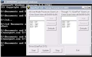
You can not directly access the parallel port in windows xp, vista etc due to the security purpose. To access the port do the following:
1. first go to the BIOS setting.
2. then select advanced option.
3. under this option select peripheral configuration
4. then change the setting of parallel port as
a. enable
b. bi-diractional
c. IRQ-7
After doing these steps download the user port and follow the instructions. A window will open, when you will run userport.exe, asking the range.
To find this:
- right click on my computer icon
- select manage
- from device manager select ports(com &LPT)
- double click on printer port
- a window will open, choose the resources tab you will find

Fill this range in both the spaces and then click on add button. Then click on start button three times, a message will appear just click ok.
Now your port is ready for interfacing.
Tutorial one:
LED Chaser:
- Connect 8 LEDs to the data port of the parallel port as shown in the figure.

- Connect ground to pin # 25.
- Copy and paste the assembly program link it (in MASM) & create .exe file.
- This program is basically LED chaser in which LEDs blink from left to right when you press ‘r’ and from right to left when you press ‘l’. to off these LEDs just press ‘ 0’ and ‘Esc’ button to exit.
Assembly code:
Dosseg
.model small
.stack 100h
.data
msg db 13,10,'Press r for right movement',13,10,'Press l for left movement',13,10, 'Press 0 to Off',13,10, 'Press Esc to exit','$'
.code
main proc
mov ax,@data
mov ds,ax
mov ah,09h
lea dx,msg
int 21h
set: mov al, 0ffh
mov dx, 378h
out dx,al
call delay
call delay
call delay
mov al,00h
out dx,al
call delay
call delay
call delay
mov al,10000000b
lop1:
push ax
push dx
mov ah,06h
mov dl,0ffh
int 21h
cmp al,27
je exit
cmp al,'0'
je off
cmp al,'r'
je loop2
pop dx
pop ax
ror al,1
ror al,1
out dx,al
call delay
call delay
jmp lop1
loop2:
mov dx,378h
mov al,01h
strt: out dx,al
call delay
call delay
rol al,1
rol al,1
push ax
push dx
mov ah,06h
mov dl,0ffh
int 21h
cmp al,27
je exit
cmp al,'0'
je off
cmp al,'l'
je set
pop dx
pop ax
jmp strt
off: mov al, 0h
mov dx, 378h
out dx, al
exit: mov ax, 4c00h
int 21h
main endp
delay proc
push ax
push dx
mov bx,00h
mov ah,2ch ;To Get System Time
int 21h
mov bh,dl ;Copy seconds into bh reg
getsec: mov ah,2ch
int 21h
cmp bh,dl
jne back ;Jump to back when get 1 sec.
jmp getsec
back: pop dx
pop ax
ret
delay endp
end main
- Tutorial two:
- Seven Segment Common Cathode Counter:
- Common Cathode means all –ve terminals of LEDs are grounded & 1 for on, 0 for off.
- Connect 8 LEDs to the data port of the parallel port as shown in the figure.
- 1st construct the table for 7-segment
Digits | Hex |
0 | 3f |
1 | 06 |
2 | 5b |
3 | 4f |
4 | 66 |
5 | 6d |
6 | 7d |
7 | 07 |
8 | 7f |
9 | 6f |
- This is basically 7-segment counter & timer in which you can set/reset, and pause it.
- If any one interested in this, he can ask me about the assembly code of this project.
Enjoy playing with parallel port.


Aoa
ReplyDeleteZohaib thanks alot...........
Well your work is very good keep it up.
Now i ll try it
Thanks again....
I'm interested please send me the code. thanks. :)
ReplyDeletehere is the link.
Deletehttp://www.4shared.com/file/xwsBAEOu/sstimer.html
Thank You. can you teach how the assembly code are working on led lights you posted here. because i want to change the way the led lights on. :)
Deletecheck register 'al'. me using rotate left "rol" and rotate right "ror" commands.
Deletehow about the push ax and push dx? and what is getsec? sorry for a bunch of question. hope you'd answer. :)
Deletemov ah, 06h what is that for?
Deletepush are used to save the content in stack. and pop for retrieve them.read "int21" operation you will know the use of 06h in al.
Deletehey. the sstimer you gave has an error. at line 50 can you check it? it says here that. sstimer.asm(50) Relative jump out of range by 0023h bytes. can you fix that? that is the only error. thanks.
DeleteYESSS! i already solved my problem. haha.
Deleteit is really need to put resistors in the 7 segment? i watch the video but i didnt see any resistors.
ReplyDeleteyou can use them. i did not used due to time shortage.
Delete