Conventionally, wireless-controlled robots use RF circuits, which have the drawbacks of limited working range, limited frequency range and limited control. Use of a mobile phone for robotic control can overcome these limitations. It provides the advantages of robust control, working range as large as the coverage area of the service provider,no interference with other controllers and up to twelve controls.
Although the appearance and capabilities of robots vary vastly, all robots share the features of a mechanical, movable structure under some form of control. The control of robot involves three distinct phases: perception, processing and action. Generally, the preceptors are sensors mounted on the robot, processing is done by the on-board microcontroller or processor, and the task (action) is performed using motors or with some other actuators.
Project overview:
In this project, the robot is controlled by a mobile phone that makes a call to the mobile phone attached to the robot. In the course of a call, if any button is pressed, a tone corresponding to the button pressed is heard at the other end of the call. This tone is called ‘dual-tone multiple-frequency’ (DTMF) tone. The robot perceives this DTMF tone with the help of the phone stacked in the robot.

The received tone is processed by the ATmega16 microcontroller with the help of DTMF decoder MT8870. The decoder decodes the DTMF tone into its equivalent binary digit and this binary number is sent to the microcontroller. The microcontroller is preprogrammed to take a decision for any given input and outputs its decision to motor drivers in order to drive the motors for forward or backward motion or a turn.
The mobile that makes a call to the mobile phone stacked in the robot acts as a remote. So this simple robotic project does not require the construction of receiver and transmitter units.
DTMF signaling is used for telephone signaling over the line in the voice- frequency band to the call switching center. The version of DTMF used for telephone tone dialing is known as ‘Touch-Tone.’
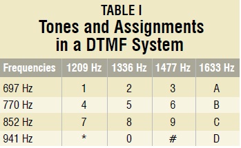
DTMF assigns a specific frequency (consisting of two separate tones) to each key so that it can easily be identified by the electronic circuit. The signal generated by the DTMF encoder is a direct algebraic summation, in real time, of the amplitudes of two sine (cosine) waves of different frequencies, i.e., pressing ‘5’ will send a tone made by adding 1336 Hz and 770 Hz to the other end of the line. The tones and assignments in a DTMF system are shown in Table I.

Circuit description:
Fig. 1 shows the block diagram of the microcontroller-based mobile phone operated land rover. The important components of this rover are a DTMF decoder, microcontroller and motor driver.
An MT8870 series DTMF decoder is used here. All types of the MT8870 series use digital counting techniques to detect and decode all the 16 DTMF tone pairs into a 4-bit code output. The built-in dial tone rejection circuit eliminates the need for pre-filtering. When the input signal given at pin 2 (IN-) in single-ended input configuration is recognized to be effective, the correct 4-bit decode signal of the DTMF tone is transferred to Q1 (pin 11) through Q4 (pin 14) outputs.
Table II shows the DTMF data output table of MT8870. Q1 through Q4 outputs of the DTMF decoder (IC1) are connected to port pins PA0 through PA3 of ATmega16 microcontroller (IC2) after inversion by N1 through N4, respectively.

The ATmega16 is a low-power, 8-bit, CMOS microcontroller based on the AVR enhanced RISC architecture. It provides the following features: 16 kB of in-system programmable Flash program memory with read-while-write capabilities, 512 bytes of EEPROM, 1kB SRAM, 32 general-purpose input/output (I/O) lines and 32 general-purpose working registers. All the 32 registers are directly connected to the arithmetic logic unit, allowing two independent registers to be accessed in one single instruction executed in one clock cycle. The resulting architecture is more code-efficient.
Outputs from port pins PD0 through PD3 and PD7 of the microcontroller are fed to inputs IN1 through IN4 and enable pins (EN1 and EN2) of motor driver L293D, respectively, to drive two geared DC motors. Switch S1 is used for manual reset. The microcontroller output is not sufficient to drive the DC motors, so current drivers are required for motor rotation.
 The L293D is a quad, high-current, half-H driver designed to provide bidirectional drive currents of up to 600 mA at voltages from 4.5V to 36V. It makes it easier to drive the DC motors. The L293D consists of four drivers. Pins IN1 through IN4 and OUT1 through OUT4 are input and output pins, respectively, of driver 1 through driver 4. Drivers 1 and 2, and drivers 3 and 4 are enabled by enable pin 1 (EN1) and pin 9 (EN2), respectively. When enable input EN1 (pin 1) is high, drivers 1 and 2 are enabled and the outputs corresponding to their inputs are active. Similarly, enable input EN2 (pin 9) enables drivers 3 and 4.
Software description:
The software is written in ‘C’ language and compiled using CodeVision AVR ‘C’ compiler. The source program is converted into hex code by the compiler. Burn this hex code into ATmega16 AVR microcontroller.
The source program is well commented and easy to understand. First include the register name defined specifically for ATmega16 and also declare the variable. Set port A as the input and port D as the output. The program will run forever by using ‘while’ loop. Under ‘while’ loop, read port A and test the received input using ‘switch’ statement. The corresponding data will output at port D after testing of the received data.
Working:
In order to control the robot, you need to make a call to the cell phone attached to the robot (through head phone) from any phone, which sends DTMF tunes on pressing the numeric buttons. The cell phone in the robot is kept in ‘auto answer’ mode. (If the mobile does not have the auto answering facility, receive the call by ‘OK’ key on the rover-connected mobile and then made it in hands-free mode.) So after a ring, the cellphone accepts the call.
Now you may press any button on your mobile to perform actions as listed in Table III. The DTMF tones thus produced are received by the cellphone in the robot. These tones are fed to the circuit by the headset of the cellphone. The MT8870 decodes the received tone and sends the equivalent binary number to the microcontroller. According to the program in the microcontroller, the robot starts moving.

When you press key ‘2’ (binary equivalent 00000010) on your mobile phone, the microcontroller outputs ‘10001001’ binary equivalent. Port pins PD0, PD3 and PD7 are high. The high output at PD7 of the microcontroller drives the motor driver (L293D). Port pins PD0 and PD3 drive motors M1 and M2 in forward direction (as per Table III). Similarly, motors M1 and M2 move for left turn, right turn, backward motion and stop condition as per Table III.
Construction:
When constructing any robot, one major mechanical constraint is the number of motors being used. You can have either a two-wheel drive or a four-wheel drive. Though four-wheel drive is more complex than two-wheel drive, it provides more torque and good control. Two-wheel drive, on the other hand, is very easy to construct.
Top view of a four-wheel-driven land rover is shown in Fig. 3. The chassis used in this model is a 10×18cm2 sheet made up of parax. Motors are fixed to the bottom of this sheet and the circuit is affixed firmly on top of the sheet. A cellphone is also mounted on the sheet as shown in the picture.
In the four-wheel drive system, the two motors on a side are controlled in parallel. So a single L293D driver IC can drive the rover. For this robot, beads affixed with glue act as support wheels.
Tip and Ring:
Most of the readers cant pass this term 'Tip' and 'Ring'; so for your convenience lets try to solve this. First of all identify the tip and ring with the help of the figure, given below, then use the DMM and apply the short circuit test to know the unknown wires.
For short circuit test select the 'buzzer' sign in the DMM then connect the one lead tip and the other with the hand frees cut wires one by one, when you hear the beep you got it! that is you wire, the tip wire. Similarly, now connect the DMM lead to ring the other with the rest of the wires and do the same. Cut the hand frees wire before the mike. I hope it ll work for you guys.
 Download: Code files
Schematic:

Component Required:
IC1 - MT8870 DTMF decoder
IC2 - ATmega16 AVR microcontroller
IC3 - L293D motor driver
IC4 - 74LS04 NOT gate
D1 - 1N4007 rectifier diode
R1, R2 - 100-kilo-ohm
R3 - 330-kilo-ohm
R4-R8 - 10-kilo-ohm
C1 - 0.47μF ceramic disk
C2, C3, C5, C6 - 22pF ceramic disk
C4 - 0.1μF ceramic disk
XTAL1 - 3.57MHz crystal
XTAL2 - 12MHz crystal
S1 - Push-to-on switch
M1, M2 - 6V, 50-rpm geared DC motor
Batt. - 6V, 4.5Ah battery
Although the appearance and capabilities of robots vary vastly, all robots share the features of a mechanical, movable structure under some form of control. The control of robot involves three distinct phases: perception, processing and action. Generally, the preceptors are sensors mounted on the robot, processing is done by the on-board microcontroller or processor, and the task (action) is performed using motors or with some other actuators.
Project overview:
In this project, the robot is controlled by a mobile phone that makes a call to the mobile phone attached to the robot. In the course of a call, if any button is pressed, a tone corresponding to the button pressed is heard at the other end of the call. This tone is called ‘dual-tone multiple-frequency’ (DTMF) tone. The robot perceives this DTMF tone with the help of the phone stacked in the robot.

The received tone is processed by the ATmega16 microcontroller with the help of DTMF decoder MT8870. The decoder decodes the DTMF tone into its equivalent binary digit and this binary number is sent to the microcontroller. The microcontroller is preprogrammed to take a decision for any given input and outputs its decision to motor drivers in order to drive the motors for forward or backward motion or a turn.
The mobile that makes a call to the mobile phone stacked in the robot acts as a remote. So this simple robotic project does not require the construction of receiver and transmitter units.
DTMF signaling is used for telephone signaling over the line in the voice- frequency band to the call switching center. The version of DTMF used for telephone tone dialing is known as ‘Touch-Tone.’
DTMF assigns a specific frequency (consisting of two separate tones) to each key so that it can easily be identified by the electronic circuit. The signal generated by the DTMF encoder is a direct algebraic summation, in real time, of the amplitudes of two sine (cosine) waves of different frequencies, i.e., pressing ‘5’ will send a tone made by adding 1336 Hz and 770 Hz to the other end of the line. The tones and assignments in a DTMF system are shown in Table I.
Circuit description:
Fig. 1 shows the block diagram of the microcontroller-based mobile phone operated land rover. The important components of this rover are a DTMF decoder, microcontroller and motor driver.
An MT8870 series DTMF decoder is used here. All types of the MT8870 series use digital counting techniques to detect and decode all the 16 DTMF tone pairs into a 4-bit code output. The built-in dial tone rejection circuit eliminates the need for pre-filtering. When the input signal given at pin 2 (IN-) in single-ended input configuration is recognized to be effective, the correct 4-bit decode signal of the DTMF tone is transferred to Q1 (pin 11) through Q4 (pin 14) outputs.
Table II shows the DTMF data output table of MT8870. Q1 through Q4 outputs of the DTMF decoder (IC1) are connected to port pins PA0 through PA3 of ATmega16 microcontroller (IC2) after inversion by N1 through N4, respectively.

The ATmega16 is a low-power, 8-bit, CMOS microcontroller based on the AVR enhanced RISC architecture. It provides the following features: 16 kB of in-system programmable Flash program memory with read-while-write capabilities, 512 bytes of EEPROM, 1kB SRAM, 32 general-purpose input/output (I/O) lines and 32 general-purpose working registers. All the 32 registers are directly connected to the arithmetic logic unit, allowing two independent registers to be accessed in one single instruction executed in one clock cycle. The resulting architecture is more code-efficient.
Outputs from port pins PD0 through PD3 and PD7 of the microcontroller are fed to inputs IN1 through IN4 and enable pins (EN1 and EN2) of motor driver L293D, respectively, to drive two geared DC motors. Switch S1 is used for manual reset. The microcontroller output is not sufficient to drive the DC motors, so current drivers are required for motor rotation.

Software description:
The software is written in ‘C’ language and compiled using CodeVision AVR ‘C’ compiler. The source program is converted into hex code by the compiler. Burn this hex code into ATmega16 AVR microcontroller.
The source program is well commented and easy to understand. First include the register name defined specifically for ATmega16 and also declare the variable. Set port A as the input and port D as the output. The program will run forever by using ‘while’ loop. Under ‘while’ loop, read port A and test the received input using ‘switch’ statement. The corresponding data will output at port D after testing of the received data.
Working:
In order to control the robot, you need to make a call to the cell phone attached to the robot (through head phone) from any phone, which sends DTMF tunes on pressing the numeric buttons. The cell phone in the robot is kept in ‘auto answer’ mode. (If the mobile does not have the auto answering facility, receive the call by ‘OK’ key on the rover-connected mobile and then made it in hands-free mode.) So after a ring, the cellphone accepts the call.
Now you may press any button on your mobile to perform actions as listed in Table III. The DTMF tones thus produced are received by the cellphone in the robot. These tones are fed to the circuit by the headset of the cellphone. The MT8870 decodes the received tone and sends the equivalent binary number to the microcontroller. According to the program in the microcontroller, the robot starts moving.

When you press key ‘2’ (binary equivalent 00000010) on your mobile phone, the microcontroller outputs ‘10001001’ binary equivalent. Port pins PD0, PD3 and PD7 are high. The high output at PD7 of the microcontroller drives the motor driver (L293D). Port pins PD0 and PD3 drive motors M1 and M2 in forward direction (as per Table III). Similarly, motors M1 and M2 move for left turn, right turn, backward motion and stop condition as per Table III.
Construction:
When constructing any robot, one major mechanical constraint is the number of motors being used. You can have either a two-wheel drive or a four-wheel drive. Though four-wheel drive is more complex than two-wheel drive, it provides more torque and good control. Two-wheel drive, on the other hand, is very easy to construct.
Top view of a four-wheel-driven land rover is shown in Fig. 3. The chassis used in this model is a 10×18cm2 sheet made up of parax. Motors are fixed to the bottom of this sheet and the circuit is affixed firmly on top of the sheet. A cellphone is also mounted on the sheet as shown in the picture.
In the four-wheel drive system, the two motors on a side are controlled in parallel. So a single L293D driver IC can drive the rover. For this robot, beads affixed with glue act as support wheels.
Tip and Ring:
Most of the readers cant pass this term 'Tip' and 'Ring'; so for your convenience lets try to solve this. First of all identify the tip and ring with the help of the figure, given below, then use the DMM and apply the short circuit test to know the unknown wires.
For short circuit test select the 'buzzer' sign in the DMM then connect the one lead tip and the other with the hand frees cut wires one by one, when you hear the beep you got it! that is you wire, the tip wire. Similarly, now connect the DMM lead to ring the other with the rest of the wires and do the same. Cut the hand frees wire before the mike. I hope it ll work for you guys.

Schematic:

Component Required:
IC1 - MT8870 DTMF decoder
IC2 - ATmega16 AVR microcontroller
IC3 - L293D motor driver
IC4 - 74LS04 NOT gate
D1 - 1N4007 rectifier diode
R1, R2 - 100-kilo-ohm
R3 - 330-kilo-ohm
R4-R8 - 10-kilo-ohm
C1 - 0.47μF ceramic disk
C2, C3, C5, C6 - 22pF ceramic disk
C4 - 0.1μF ceramic disk
XTAL1 - 3.57MHz crystal
XTAL2 - 12MHz crystal
S1 - Push-to-on switch
M1, M2 - 6V, 50-rpm geared DC motor
Batt. - 6V, 4.5Ah battery
Very nice project! but my interest lies elsewhere. Could you tell me what CAD tool did you use for the schematic?
ReplyDeleteThank you!
Thanks. Most of the Schematics are design in proteus isis, just change the template settings or define your own template.
ReplyDeleteHi
DeleteWhere would I purchase this project complete ready to go out ofthe box.
Charlie
hi malik i will be glad if u can post a cell phone jammer circuit urs projects are super koooooooooool
ReplyDeletei have a doubt about this circuit when a 6v 4.5ah battery is used, will it not damage the microcontroller so are we supposed to add any kind of regulator or sumthing?
ReplyDeleteYou can also use two supplies. one, regulated 5v, for microcontroller and other, 6v or 12v, for motor driver; for smooth running of motors.
ReplyDeletesalam
ReplyDeletemalik bhai there is a prob that from where i could get geared dc motors.actually i could not find it.
and can you place the pcb of this circuit here
ReplyDeleteYou can bye dc motor From toy (RC Planes) shop.
ReplyDeleteActually i don't have pcb right now.
what do i do to send a command from microcontroller to mobile phone
ReplyDeleteIn this case you have to send commands from mobile phone via keypad to ucontroller, not vice versa (from ucontroller to mobile).
ReplyDeletesir can you tell me.is it work by hold keypress turn on release turn off.can you tell me how to connect relay and use all cellphone keypad available for channeling relay.for this relay i going to run 9v dc motor.and estimate of the cost to build.waiting for you respon.thank you
ReplyDeleteBasically to operate it you have to dial the phone number of attached mobile phone with the other phone. Then you have to hold the key of later phone to move the robot.
ReplyDeleteYou can interface keypad of other phones as well. All works on DTMF.
Relay can be connected at the output of the IC1. By using relay you dont have to hold the key.
4 output but the keypad contain 12 number.how to complete this.thank you again
ReplyDeleteYou concern is only with keys 2, 4, 6, and 8; refer to table 3. That is why four output! Consider others as don't care.
ReplyDeleteMalik vai,
ReplyDeleteI m using the same connection but by DTMF part is not working. I have checked the ATMGA and motor controller ic by giving manual input of binary signals, they worked fine. but DTMF part is not working. i checked the following
1. singnal is comong from mobile head phone (I cheked the signal at ic pin usnig multimeter)
2. corresponding connection
3. CM 8870 working fine
4. 3.579 Mhz crystal working
so is there any other thing i missed? plz give ur king suggestion
he.. will u suggest me which mobile should b used and how to attach that mobile with the circuit...
ReplyDeletecan we use 500 to 1000 rpm dc motor??
ReplyDeletewill it require some other programming??
upto what maximum volt and rpm we can use for this project?
If the signal from your mobile is coming then Check your connections again (Tip and ring connection of mobile etc).
ReplyDeleteCheck the output of atmaga.
You Can use any mobile (but it should have DTMF)like Nokia 1110, etc. Refer to for connection: http://en.wikipedia.org/wiki/TRS_connector
You can use any dc motor. But the Maximum voltage should not exceed 5 to 6v. No for this small project no further programming is required.
Although you can programme whatever you want.
Have fun.
plz,tell me future scope of this project.
ReplyDeleteThis is just a hobby project. You can use camera on it and by using DSP it can be used for surveillance, and security etc. Its up to you.
ReplyDeleteif we use metal detector in this project, then how it can be used at the borders for disposing hidden land mines?
ReplyDeletei m making a robo as below shown-
ReplyDeletehttp://static.howstuffworks.com/gif/military-robot-22.jpg
i want to use 4 motors for this project and i m bound to use not more than 24V battery. so how to connect 4 motors using 24V battery an i need speed of 2-3 feet/second. i want to use high rpm motor, so what rpm motor would be perfect for this? plz specify connections also as i m weak in electronics.
i m confuse that u r telling to use only 4-6V but i wud be needing more voltage, so can i use 24V battery in your ciruit and how to use it ? 1 more doubt is, u had mention only 2 motors in your circuit but i need 4 motors so plz help me out for this..
in the above shown image, there are small turning pairs so plz explain me what mechanism is ther between them while turning a tank robo???
For metal detector it can only locate the mines but to dispose you have to destroy them; it can be done by using small amount of explosive and place them on the mines; determined by the robot, then by using remote control just explode the explosive.
ReplyDeleteYou gonna be kidding me!!!!!!!!!!!!!!
ReplyDeleteFirst if you wanna use 24v then go ahead but not to forget to isolate your microcontroller and other circuitry, that runs on 5v, for this purpose just use opto-coupler.
To move 2-3 f/s; first choose the motor type like bldc, servo etc according to their specification, then calculate it.
Google it there are lots of circuit for driving the motor but its also depend upon your motor type.
As i mentioned earlier you can use 24v but with isolation.
If you want to use this circuit then use another L293 and connect it to any five pins of atmega (as in schematic)but you have to code it for this modification.
Simplest method is to motors in bi-directional; for forward and backward movement, where as for turning just adjust the speed of the motor. For example if you wanna turn left then slow the speed of left motor and increase the speed of right motor that it.
I hope it will help you.
so which microcontroller should be used????
ReplyDeleteu mean to say that i cant use your circuit for 24V motor???
"If you want to use this circuit then use another L293 and connect it to any five pins of atmega (as in schematic)but you have to code it for this modification."
i m not understanding thz?
which pins u r talking about?
yor code will not work for thz??
i m fully confused plz help me out..
if possible give your cell number.
Ok.........
ReplyDeleteFirst its your choice; use whatever ucontroller and design appropriate circuit to accomplish your task.
2nd the above circuit is made only to control two motors not four; that is why you have to use another L293 to control the other two motors. So you need to connect L293 to the ucontroller pins.
3rd my code will not support this. You have to modify the code as well.
My suggestions are; first learn the basic electronic, try to play with circuit and then go to the advance design.
If your are fan of robotics then try the simplest "line follow robot". (just google it)
When we make a call to the mobile phone attched to the robot and then robot is operate automatically. but if another subsciber call on the mobile phone atteched to the robot then what is done?
ReplyDeleterobot is operate itself or not?
THANX ELECTRONICS FOR EVERYWHERE AS U PROVIDE ME TO DESIGN A PROJECT......
ReplyDeleteIf the attached mobile is set to auto-answering option then any subscriber can activate the robot by just calling it.
ReplyDeletebut it is the disadvantage,
ReplyDeletehow it is solve?
plz give me solution for this.
ReplyDeleteYes a sort of, but also depend upon your mobile set. Means in call option just create a list from you want to receive the calls (if your mobile supports). And add the numbers of your choice, that can operate the robot, in the list.
ReplyDeleteSorry, I still don't understand how to connect the "Schematic" with the cell phone like N1100. Plz show me more detail. Many thanks
ReplyDeleteJust connect with mobile headset's speaker pins.
ReplyDeleteOR use mobile that supports hand-free, then connect the wires (Tip and Ring)with respective hand-free wires.
http://en.wikipedia.org/wiki/Tip_and_ring
we've connected only dtmf ic part on a bread board..we've used MT8870 decoder ic.. we've checked the ear phone using multimeter...we are using 6v..4.5ah battery...but the binary output is not coming when we make call at the outputs of decoder ic...all outputs ie pin no 11,12,13,14 are high(6v) always...pla give a solution,,,we are frustrated
ReplyDeleteOutput of 8870 should be the binary value of the corresponding key (pressed). Make sure your phone should have dtmf (some time error is due to this reason). Also make sure u using original dtmf decoder ic, cheap ic's doesn't respond well for some buttons (there are lots of tester available on net).
ReplyDeletewe are using nokia 6303 and 3110c.....also how to test 8870 ic...we replaced that ic with cm8870...but problem still persist...
ReplyDeletewhenever a call is made..when we press keys all outputs remain high..is there any prob with earphone...pls tell us the standard method for testing earphone after cutting it.. we gave 5v to tip..and measured voltage on the other side n identified tip...and ring in the same way..is this wrong method
ReplyDeleteTo test 8870 google it. or check this link:
ReplyDeletehttp://www.electronicsforu.com/efylinux/circuit/jun2003/ci-2-dtmf.pdf
It seems you are not getting the dtmf signals at all, fault could be in your ic or you are not correctly able to identify the tip n ring.
Usually tip is +ve, and ring is either -ve, or ground. Use multi-meter and check the voltage of tip and ring with respect to the ground (earphone should be connected to ur cell).
Also check this:
http://www.suite101.com/content/how-to-wire-a-jack-plug-or-audio-phone-jack-plug-a106033
in this proj why we've to use ATMEGA 16 microcontroller...we can use 8051 also right?? any advantages of tat over 8051??
ReplyDeleteIn this scenario no advantage. Yes, you can use 8051 or whatever you wanna use.
ReplyDeleteright now we've 4 controls forward,backward,right,left..can we add some extra using atmega 16 mc...pls suggest some other controls which are useful
ReplyDeleteYes Stat, Stop, and speed control; if u want.
ReplyDeleteyes we r using stop. for speed control we just need to modify code or any other hardware needed?..................also pls suggest some more useful controls which ve real time applications...pls
ReplyDeleteNo just choose a button, say 0, and compare it; this is for stop.
ReplyDeleteAnd for speed control, generate software PWMs.
In both cases you have to change your code.
which software and kit we've to use to burn atmega 16 avr mc
ReplyDeleteWhile running this project we accidentally short circuited the PCB. Now it is not working. Could the short circuit damage the ICs or the AtMEGA??
ReplyDeleteWe are using Nokia 1110 on the board and SE Walkman to send the dtmf.
Thankyou
I think so.
ReplyDeleteSaperate thr ics; apply power and input pattrens. If u get result;ics are ok.
does it require 12 v for l293d to drive 50 rpm motor or only 5v enough?i need the robot to go faster and which software and kit we've to use to burn atmega 16 avr mc
ReplyDeleteYou can if you want. But have to isolate the other 5v circuitry. I think it was an old universal programmer(i dont have avr programmer, i did this in college).
ReplyDeleteSir can u post the source code used in AVR for controlling the vechicle?
ReplyDeleteCan we use single motor for all d 4 movements?
ReplyDeletesir plz tell me that can i burn the hex file directly into the microcontroller that u given in link above(download:code files) or is it need some modification becoz someone tell me that it is not a complete program that u given in c language.... will my project work by burning directlythe hex program u given please please guide me
ReplyDeletemany many thnx
For 4 movement, you need 3 motors.
ReplyDeleteone for forward and backward, and other two are for left and right movement.
The code is complete for these four movements. But you can modify it according to your desire.
thnx for ur reply
ReplyDeletesir
we design our pcb exactly as u given in the circuit diagram....but when we connect battery of 6v,4.5Ah at the end of the motor driver as u shown in the circuit diag. our mototor driver is burned out...plz tell me sir why is that so???
sir if our motor driver is burned thn is it also effect our microcontroler or not
ReplyDeletesalam bhai
ReplyDeletecan u tell me how i will check my controller individually that weather it is working or not????? thnks a lot
sir can i ask my questions in hindi for my better sayisfaction will u reply me in hindi???
ReplyDeleteMay be you short your pcb or motor power rating is low; use small battery if so.
ReplyDeleteTo check your ucontroller just apply input patterns and check the corresponding o/p.
I don't know hindi.
how we know sir that controller in programmed correctly?
ReplyDeleteSir if i have to carry a load of 300g on this vehichle, what would be the specifications of the motors i should use?
ReplyDelete"how we know sir that controller in programmed correctly?"
ReplyDeleteJust apply i/p and check the o/p, if it is according to its functionality(left, right etc) then its ok.
Use the motors that can handle this much load. Simple!!!!isn't it???
use motors with slight high power rating.
Upto how much power & voltage the ic L293D supports?
ReplyDeletePlease refer to its datasheet.
ReplyDeletesir my circuit is complete as u shown in the ckt. diag. but it is not working...in order to firstly check my mt8870 decoder m connect the LED with 11,12,13,14 pin of the decoder with respect to ground....but my LED remain glow even i make cl or not....pls tell me sir whr is the problem or is it a right way to check
ReplyDeletethe decoder..... if not so plzz tell me how can i check my decodr in present conditions
sir i m new in this project n i have one que in my mind tht if individual dtmf decoder glows the LED by recieving a call n pressing 2,8,4 n 6 thn why we need programming through microcontroller in this ckt ??/
ReplyDeletesir i read this link tht u given 4 the decoder testing http://www.electronicsforu.com/efylinux/circuit/jun2003/ci-2-dtmf.pdf
ReplyDeletebut this link is for the testing by landline phone...but m completed my ckt. already so plzz tell me a suitable method fo testin me decoder i present condition
hello ..we did all cktry and got op also but now we r trying to use 4 motors ..for tat we r using 12 v power supply..will it work?? since we r using many ics wont it load battery?? wen we used 5v supply..all dtmf op LEDs were going high..now we r giving 12v to pin 8 and 5 v to pin 16 of l293d...will it work...pls help...pls answer both questions...pls pls
ReplyDeleteFirst please specify ur names so i easily address u.
ReplyDeleteBecause u need to drive the motors using driver and can't just use the o/p of decoder to run them, although u can do that but it will not b the good approach; to make it versatile u need a mc(so u can modify it according to ur demands).
For landlines or cellphone the frequencies will remain the same, circuit should have to work.
It depends upon ur motors, where as for l239d it can work till 36v; so no need for two different supplies. You should use the supply that can able to meet the current requirements.
thanks..but when we used 5v supply for pin 16 and 8 of l293d..motors run but when we press other button on phone...all dtmf outputs ie leds go high..and remain same till we remove motors..after tat it responds to key pressed..wats the prob
ReplyDeletehow to connect mobile to dtmf decoder ....
ReplyDeletei mean what are the connections made in cellphone to connect with dtmf decoder.....
after cutting earbuds of my headphone i am getting a blue and a black wire with copper wire wrapped on both these wires.do i need to seprate the copper wire and connect only the thin blue wire?is the blue wire the tip and the red wire ring?please help sir i need to complete my project before 4 may 2011 as my college project .i have checked every other part of my circuit but the dtmf and headphone part is not working properly
ReplyDeleteASHISH
PLS TELL ME 8051 IS ERASABLE OR NOT...HOW MANY TIMES WE CAN BURN INTO IT
ReplyDeletewe accidentally gave 12v to atmega16 ic....is it gone or if we burn prgm to it again will it work....pls answer???
ReplyDeleteYes, 8051 is erasable.
ReplyDeleteYou have to check its o/p, if no o/p means u have to buy new one.
atmega is giving outputs but they wont match with correct outputs..also enable ie pin 21 is always high...and if we want to use 8051 in place of atmega wat changes we've to made...pls tell...as atmega 16 is costly...and we've already soldered all connections of project.....so pls specify is it good to change to 8051 now
ReplyDeletepls reply soon as we've to submit project in 10 days pls....thanks in advance sir
ReplyDeletepls specify if we need to change c code if we use 8051
ReplyDeleteIt is more likely that the problem lies in CM8870 ic, as most of these ics does not response; don't know why? may be manufacturing fault?.
ReplyDeleteIf u wanna use 8051 u have to change the i/p and o/p instructions; to make the port either for input or for output purposes.
sir we are not getting dtmf outputs properly. i mean when we r pressing nos continuously for one no we get randomly...but for next no it wont come...if one op comes it gets latced and dont change till we remove supply and reconnect it....earlier it was coming correctly...but now this prob....its coming correctly on bread board but with different components and same ic.....wats the prob...pls help....also is there any prob with 3.57MHZ crystal used..ic is ht9170b
ReplyDeletehmmm sir i hav made a program for 89c51 for this project dat runs in keil software....it is ok der...so can we use dat program?....and one more question do we need to install the NOT gate ic when we are using the 89c51 ic....??....and why the NOT gate ic is installed in the ATMEGA contrler circuit....??PLEASE REPLY
ReplyDeleteNikhil!...
sir please its urgent!!!!
ReplyDelete?????????????????????????????????????????????????????????????????...Nikhil
ReplyDeletesir in this project why they ve used not gate between decoder ic and microcontroller........pls tell us...we've project seminar .pls pls
ReplyDeletenormally the o/p of mt8870 is high, ic is used to differentiate between the outputs. you can eliminate this ic but u have to change the design and code as well. instead of pulling up, pull down through resistors and then compare for inputs.
ReplyDeletebut for pin 1 and 2 of the 89c51 we dont need pull up resistors...so it is ok if we dun use the not gate ic....??the circuit design will be same na just without the not gate ic and resistors....??
ReplyDeletenikhil
only port0 need pullup in 8051. if you don't wanna use not ic; just remove it along with the pullup resistors and directly read the mt8870 output through programming.
ReplyDeleteokey after complition willl definatly tell ya... thanks!
ReplyDeletenikhil
Mercedes-Benz will be offering a mobile-phone holder for the Nokia
ReplyDeletehello sir..
ReplyDeleteiam Priyatham...
very much interested in your project,and try it do as my mini project with slight changes..iam trying to interface a stepper motor..could you plz tell me..what is the software you have used to generate hex file for ATMEGA16 uC...
thanks :-)
http://www.subtours.com/ralph/theory/atmega16witharduino.html
ReplyDeletesomehow like that, but i don't remember exactly; old times.
sir can i use nokia2626 and please give me hex file of this project
ReplyDeleteAre you kidding????
ReplyDeleteHex is inside the folder, in download section.
i have connected tip(left) and ring(right)...should the sleeve(ground) of the stereo jack also be connected to the circuit?(if yes, then where?)
ReplyDeletesir pls tell us how to know about design of this ckt..ie why only this resistor is used 10k for pull up,and why diode is used and why capacitors are used for crystal?? any software to simulate all this...pls help
ReplyDeleteHello sir...
ReplyDeleteIam Priyatham
sir could you please suggest me a cell phone through which,i can be able to use all the keys to control the robot and including some extra features.
can NOKIA 1100 be used to serve the purpose..
HELP!
Thanks in advance
Yes, you can use it. Most of the time the problem is in DTMF decoding ic; is better to check the ic first.
ReplyDeletesir
ReplyDeletewe hav completed this above robot
working fine
but we r told to add extra functions to this robot....
can u sujjest some other applications to this project??
pls help
thanks...
i want atleast 1 more application to this robot...
ReplyDeletepls pls pls help....
you can use camera or can make it mine/metal detector robot.
ReplyDeletehey ... i wanna simulate a ckt in proteus and it uses mt8870 but i cant find it in library of proteus..........wer can i find it?? or any ideas how to use mt8870 in proteus......plz help
ReplyDeleteYes there is no library for this ic. But you can make it by your own, but i am not sure that it will simulate that.
ReplyDeleteCAN IT BE DONE WITH A 8051 PROCESSOR
ReplyDeleteHi its really very nice blog i enjoyed a lot to visit..
ReplyDeletesir i am try to cell phone operator land rover my kit dint not work,how to connect head phone to kit,tip and ring is correctly connected but my nok6300 is not show headset symbol wht reson sir pls help me sir
ReplyDeleteFirst explain the kit you are using. tip and ring connection can easily be found on internet via google.
ReplyDeleteGood Day sir,
ReplyDeleteI like this blog very much, I have learned much out from this site.
amh,
can I use PIC Microcontroller instead of ATmega16
and what PIC can u suggest???
Are there any changes on the program flow except to those FSR names of Atmega16??
thanks,
Jonathan Louie
Yes you can use the PIC. you can use PIC16F628. No just the SFR namse.
ReplyDeletesir can i use nokia2626 and please give me hex file of this project
ReplyDeletesir,
ReplyDeletei want a high speed land rover robot controlled by cellphone as per the requirement of our project. can u please kindly suggest me some method to increase the speed of the landrover robot u have described in ur blog.
thanks
Speed depends on what type of motor you are using.
ReplyDeletefor more speed use high rpm motor.
why have u used a not gate at the input of u-controler from the output of 8870.. plz rply asap .
ReplyDeleteif we used logic gates in place of microcontroller......application will change or not????
ReplyDeleteNot recommended, but you can do that. You have to design a gate circuit whose o/p exactly behave like the o/p of controller according to the i/p.
ReplyDeleteSir i would like to get pcb to interface a mobile phone with mt8870 ic.Besides, only 4MHz crystal is available in my country.
ReplyDeleteplz mail ramzalay@googlemail.com. thz.
ReplyDeleteI COULD NOT UNDERSTAND,WHY SHOULD U USE THIS "NOT GATE" BETWEEN DTMF & MICROCONTROLLER PLZ EXPALIN.
ReplyDeletehello i do this project. it is nice but i used mt8870BE. it is working . but 1,2,3, number not working and 4,5,6 is badly working. other numbers good working . pls help me to solve 1,2,3,4,5,6
ReplyDeletemay be tone frequency issue of mt8870be. the frequencies of both ics are same or not???
Deletegood project!but i need your help,when i want robot to go ahead i just press and hold "2" and it stop when i release key "2",right?please reply me as soon as you can.thank so much!
ReplyDeleteyes you are right.
Deletewhy is NOT GATE used in the circuit?if i use 8051,should i connect NOT GATE or not?plz show me how it work!friend.
ReplyDeleteno; you can directly interface the MT8870 with uC. if you do that then you have to change the little bit coding.
Deletehow to program atmega 16 please help me in this issue
Deleteunfortunately i dont have any schematic of it. google it, i hope you will find plenty of them.
Deletesalam malik bhai,
ReplyDeletemyself badal,
I am doing same project for my college project.
I did above connection properly and give output to led through atmega with delay of 1 min to hold leds but I pressed
any key all led glow
I checked tip & ring connection with DMM .
we are using NOKIA C1 for our project
or should i use another cell phone???
please reply fast
are you connecting LEDs on portd? make sure you are properly using portd bits;not all high at a time.
Delete...I am facing trouble doing this coding with PIC 18f452...plz help me with ur tips/advice/codes...mail me asap...have to finish it within this week :(
ReplyDeletesaurov1159@yahoo.com
what kind of trouble???
DeleteHi I am a student and I am working with this project. But i can not decode DTMF signal. Because when i cut headphone wire I see that there are three colored wire GOLDEN, BLUE and RED. can not identify the RING and TIP wire. Please Please Please give me some advice or circuit diagram that I can connect RING and TIP to MT8870 DTMF decoder IC. And also actually where I cut the headphone wire after MIC or before the MIC. Please Please Please give me some advice. I want to complete my project.
ReplyDeletePlease mail or contact me:
akash.cse.du@gmail.com
or
shaylakash@ymail.com
which mobile phone you are using??
ReplyDeletecheck this link:
http://www7.taosnet.com/ebear/colorcodes.html
Hi,i am also working with akash...
Deletewe are using Nokia x1-01
Its not working...actually we are confused about the headphone wire connection in decoder
please help us
thanks..
Malik Zohaib or Administrator Vai can you give your any contact ( Mail or Fb ) we want to communicate with you. Please help us :(
DeleteCan you suggest any mobile model. And where we cut the headphone wire after the MIC or before the MIC ?
ReplyDeletei update the post read the 'tip and ring' paragraph.
DeleteCan you suggest any mobile model or we can use Nokia x1-01 ?
Deleteyes you can use. whats the problem?? still stuck in tip and ring???
DeleteYes we can not identify the tip and ring in the headphone wire. Please help us please.
DeleteMalik Vai can you give your any contact ( Mail or Fb ) we want to communicate with you.
Please help us please. :(
when I cut my headphone I found 3 wire red,green,gold. i can not identify which wire i connect to which pin in mt8870.
ReplyDeletei already mentioned; perform continuity test using DMM to identify them.
ReplyDeleteThanks Malik vai we complete this project successfully .... :D
ReplyDeleteNASRATH: hello sir...our dtmf part is working very fine..after that we wrote a code for 89c61x2 microcontroller and loaded onto it ..but on connecting it to the circuit we r not able to get the output...sir, may i know
Delete* wy the pull up resistors are used ? if it is necessary to connect it ?
* how to check out the output at the end of the microcontroller ?
* how to connect the reset pin and wats its significance ?
* plz..plz..reply, its very important for us...we need to submit it at the end of this month...
Reply
This comment has been removed by the author.
ReplyDeleteSir ! How can we use a password protector for a design like this
ReplyDeletehiii...to connect some aditional features like camera,gps etc how do we connect in the circuit????plzzz replyyy
ReplyDeletemalik zohaib can u give me ur emailid i wana chat wid u on this topic and want to make a project would u help me out wid this
ReplyDeleteis it possible to build that project without using a micro controller let us for those who doesn't know how to program
ReplyDeleteSo true, and what’s perhaps even more devastating is that there’s been so little support to help the community rebuild.
ReplyDeleteLand Rover Australia
need any programming????????
ReplyDeletereplay pls...........
yes; download the code program the uc using hex file.
DeleteNASRATH: hello sir...our dtmf part is working very fine..after that we wrote a code for 89c61x2 microcontroller and loaded onto it ..but on connecting it to the circuit we r not able to get the output...sir, may i know
ReplyDelete* wy the pull up resistors are used ? if it is necessary to connect it ?
* how to check out the output at the end of the microcontroller ?
* how to connect the reset pin and wats its significance ?
* plz..plz..reply, its very important for us...we need to submit it at the end of this month...
Read the above comments you will find your answer. Regards.
DeleteHi! Please please send circuit PCB. Lysenkokolya@yandex.Ru Thank you.
ReplyDeleteHello Sir..how to pulse width modulate the atmega 16...do we need to change anything in the code??...i am trying to control the speed of the bot from the mobile...if so wat wil be the change in the code...help me plessss....
ReplyDeleteHello Mr. Malik,
ReplyDeleteThank you for your interesting project. I am also excited about this project and i want to do this. But before i implement practically, I want to simulate in software. Here i can't find DTMF decoder MT8870 ic in proteus isis. Is there any other option or any other simulation software i can find this ic?
Thank you.
Check this link:(copy n paste the url)
Deletehttp://www.edaboard.com/thread162908.html
HI MALIK Bhai,
ReplyDeleteIs there a way to use this circuit to controller other appliance like radio,television or light bulb etc instead of a Robot? If you so can you show me how and the circuit diagram to be implemented.
Thank you for your coopration.
removes motors, and l293. use relay and transistor(as relay driver),if you just want on and off the appliances, change the code; thats it.
Deletehi can i do this with an arduino uno?? if yes then can u please give the complete circuit?
ReplyDeleteyou can use any other micro-controller; you just have to write the code accordingly.
Deletei can't download the code.my email address is mamun_a27@yahoo.com
ReplyDeleteI want to make this project on Arduino.
ReplyDeleteIs it possible on Arduino??
If possible, then on which Arduino..????
PLZ send me detail on apnaemail505@gmail.com
sir can u give me the pdf file of this project on my email id {kalpeshpatil0004@rediffmail.com} we want to prepare the mine dectector with auto diffusing can you suggest me some points about my project????
ReplyDeleteSir,myself Pooja......i ma making cell phone operated land rover using atmega16a....all the parts are individually working well, but i getting high o/p for every input from pin14,15,16,17 of atmega16a .....is it programing error??? there is any difference b/w atmega16 and atmega16a....please send me code for atmega16 or atmega16a on my email...poojakumari28jan@gmail.com
ReplyDeleteYou can interface keypad of other phones as well as Realme mobile phones pakistan
ReplyDeleteThanks for sharing this information about cellphone-operated Land Rover, which is an interesting innovation that showcases the possibilities of technology. It should be available in brands like, Oppo smartphones. It would be a great device to use for controlling the Land Rover, thanks to their fast and reliable performance.
ReplyDeleteThis is a fascinating project! The integration of mobile technology to control a Land Rover opens up so many possibilities. It's amazing to see how innovation in the electronics field can transform everyday vehicles. By the way, if anyone's interested, they can check out the latest mobile phone prices in Pakistan for more tech updates!
ReplyDeleteBest Car Chargers and Mounts services Surrey
ReplyDeleteCar Chargers and Mounts in Abbotsford