The glow plug controller (Fig. 1) uses a simple timer circuit built around MOSFET T1 for reliability and simplicity. Momentary pushing of switch S2 charges capacitor C1 rapidly via resistor R1. When the voltage on capacitor C1 exceeds the threshold voltage of the gate (G) of MOSFET T1, it starts charging reservoir capacitor C2 and simultaneously energises relay RL1. MOSFET T1 remains conducting as long as the voltage on C1 is greater than the threshold voltage of the MOSFET gate.
The ‘on’ time period depends on the value of capacitor C1 and resistor R2, which govern the discharge current of capacitor C2. The component values given here will produce ‘on’ time of around 25 seconds. In effect, when you
press switch S2 momentarily, the relay energises for about 25 seconds and the glow plug gets the power supply through its contact.
The red LED (LED1) indicates that the heating process of glow plugs is ‘on.’ When the ‘on’ time is over, the green LED (LED2) turns on for a while, followed by a short beep from the buzzer, which indicates that the engine is ready for starting. Glow plugs draw a heavy current, hence high-current rating contacts of an automotive relay are required.
Assemble the circuit on any general purpose PCB and house in a suitable case. Connect the glow plug wire to the relay contact. 12V battery already available with the vehicle is used to power the circuit. Connect the piezo buzzer and LED1 and LED2 through an external connection and place it at a convenient location for the driver to operate.
Schematic:
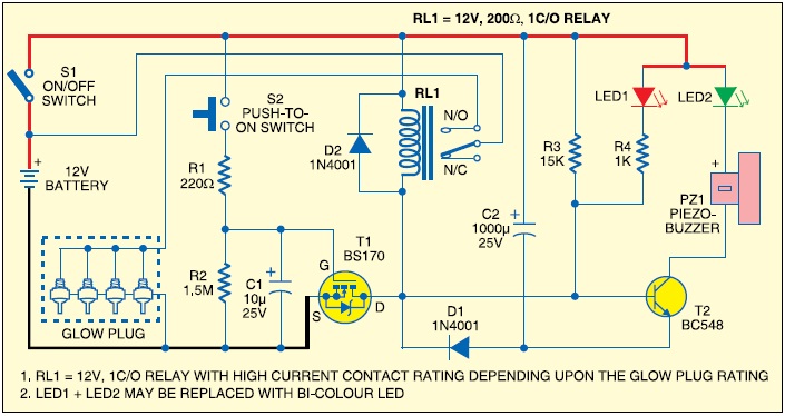 |
| Fig. 2. Glow Plug Controller |

R1, 220 ohm
R2, 1.5M ohm
R3, 15K ohm
R4, 1K ohm
D1, 1N4001
T1, BS170
T2, BC548
C1, 10uF/ 25V electrolyte
C2, 1000uF/ 25V electrolyte
PZ1, Piezo Buzzer
S1, on/off Switch
S2, push to on Switch
LED1, red LED
LED2, green LED
RL1, 12v High current
i want to build this circuits for my tractor but whit a 7 second delay is it possible and what would i have to modify thanks a lot
ReplyDeletemartin
its already taking about 25s; can be adjust by changing R2 and C1 values.
Delete