Friday, December 21, 2012

12V-24V High-Current Motor Speed Controller Part-3

In first part we discussed about the detail of circuit, back EMF and Mosfet protection; and in second part we covered the display and menu, in this third and last part we will build and test our project. 

The DC Motor Speed Controller is built on two PC boards: a main board, and a display  board. These are joined together via a 12-way flat ribbon cable, which plugs into a pin header on the main board. 

The main board can be assembled first – see Fig.9. Start by checking the PC board for hairline cracks and for any visible shorts across the copper tracks, especially between the ground plane and any adjacent tracks. In addition, check the hole sizes for the larger hardware items by test fitting these parts into position.

Making a link
That done, begin by installing the 17 wire links. These must go in first, since some of them run underneath some components.


To straighten the link wire, first clamp one end in a vice, then stretch it slightly by pulling on the other end with a pair of pliers. It’s then just a matter of cutting the links to length and bending their leads down through 90° to match the holes in the PC board.

Saturday, December 15, 2012

12-24v High Current Motor Speed Controller Part 2

In first part we discussed about the detail of circuit, back EMF and Mosfet protection; in the second part we will cover these:

Other protection measures
As already mentioned, diode D1 provides reverse polarity protection for microcontroller IC1 and the switchmode supply (IC2). Zener diode ZD1 is self-protecting in the case of reverse supply connection. However, if the supply is reversed, there will be a heavy conduction path via fast recovery diode D3 and the internal substrate diodes in the four power MOSFETs. If you are lucky, the 50A fuse will blow before the MOSFETs are damaged, but there is no  guarantee of this. SO dOn’T rEVErSE THE bATTErY cOnnEcTIOnS!


In a similar vein, if the outputs are shorted while power is applied, high current will flow  through the MOSFETs. Again, if you are lucky, the 50A fuse will blow before the MOSFETs go up in smoke. In reality, the 50A fuse is there to stop a fire! SO dOn’T SHOrT THE OUTPUTS TO THE MOTOr.


If the motor is under heavy load and becomes stalled, high currents will flow in its armature.  Depending on the motor’s rating, this may or may not blow the fuse. If the fuse  does not blow during stall conditions of the motor, the MOSFETs should survive, although they may get very hot.

Saturday, December 8, 2012

DIY Desktop-Table LED Lamp


Hi guys lets do something woody!!! something you may wanna do!. If don't then,.... what can i say its your choice.Ok lets get started.
In this DIY i ll tell you the story of my diy wooden desktop and wall led lamp. So first of all the things required are: 1)round slick/rod of one inch dia.
2) Some nuts n bolts 

3) some washer 
4) 24 High bright LEDs 
5) 8 100ohm resistors 
6) 12v adaptor 
7) small piece if MDF board 
8) on/off switch
9) piece of flat thin wood (as you can see in fig bellow, actually i don't know the name of this wood!!! ) 

Thin Wood stick n round wood piece

Saturday, November 24, 2012

12-24v High Current Motor Speed Controller Part 1

 This 12V or 24V high-current DC Motor Speed Controller is rated at up to 40A (continuous) and is suitable for heavy-duty motor applications. All control tasks are monitored by a microcontroller and as a result, the list of features is extensive.

This high-current motor speed controller is based on a PiC16F88 microcontroller. This micro provides all the fancy features, such as battery monitoring, soft-start and speed regulation. it also monitors the speed setting potentiometer and drives a 4-digit display board, which includes two pushbuttons.

The 4-digit display board is optional, but we strongly recommend that you build it, even if you only use it for the initial set-up. it unlocks the full features of the speed controller and allows all settings to be adjusted.

Thursday, November 1, 2012

AVR ISP ScoketBoard

Most Atmel AVR microcontrollers can be programmed via their in-built serial programming interfaces (SPI). This method is ideal for in-situ programming, such as might be used in manufacturing or for firmware development or field upgrades.

In this scenario, the micro remains in its socket on the application board and a low-cost in-system programmer (ISP) is plugged into a dedicated programming header. In other words, the microcontroller does not have to be removed from its socket and plugged into a parallel programmer each time a firmware update is required.

However, in some cases it is desirable to programme a microcontroller stand-alone, such as when the application board is unavailable or doesn’t include an ISP (or JTAG) header. A low-cost method of stand-alone programming might also be useful where a batch of chips is needed for a small prototype run and the cost of a commercial parallel programmer is prohibitive.

Saturday, September 15, 2012

Phase Angle Control Of SCR Using AT89C51

Silicon-controlled rectifiers (SCR) are solidstate semiconductor devices that are usually used in power switching circuits. SCR controls the output signal by switching it ‘on’ or ‘off,’ thereby controlling the power to the load in context. The two primary modes of SCR control are phase-angle fired—where a partial waveform is passed every half cycle—and zerocrossing fired—where a portion of the complete waveforms is passed to regulate the power.

In the phase-angle controller, the firing pulse is delayed to turn on the SCR in the middle of every half cycle. This means that every time a part of an AC cycle is cut, the power to the load also gets cut. To deliver more or less power to the load, the phase angle is increased or decreased, thereby controlling the throughput power.

There are several ways to control the firing angle of SCR. This article describes a microcontroller AT89C51-based phase-angle controller. A microcontroller can be programmed to fire SCR over the full range of half cycles—from 0 to 180°—to get a good linear relationship between the phase angle and the delivered output power.

Some of the features of this microcontroller-based phase-angle controller for SCR are:

1. Utilises the zero-crossing detector circuit
2. Controls the phase angle from 0–162°
3. Displays the phase angle on an LCD panel
4. LED indicators are used for displaying the status of SCR
5. Increases or decreases the phase angle with intervals of 18°

Basically, the zero-crossing detector circuit interrupts the microcontroller after every 10 ms. This interrupt commands the microcontroller to generate some delay (in the range of 1ms to 9 ms). The user can increase or decrease the delay in intervals of 1 ms using switches. the SCR is then fired through the opto-coupler. This repeats after every 10 ms.

Saturday, September 8, 2012

Solar LED Lantern with battery charger

This solar LED lantern can be used as an emergency light. Its 6V battery can be charged either from 230V, 50Hz AC mains or a 12V, 10W solar panel. Two LED indicators have been provided—red LED (LED1) indicates battery charging and green LED (LED2) indicates fully-charged battery.

You can choose to charge the battery either from the mains power or the solar panel by using the single-pole, double-throw (SPDT) switch. Capacitor C1 (1000µF, 35V) removes ripples from the power supply and regulator IC LM7809 (IC1) provides regulated 9V DC to the emitter of pnp transistor T1 (TIP127/BD140) and pin 7 of op-amp IC CA3140 (IC2), which is configured in comparator mode.
 The reference voltage of 6.3V at pin 2 of IC2 is obtained through the combination of resistor R7 (1-kilo-ohm) and zener diode ZD1 (6.3V). The comparator controls charging of the battery. Pin 3 of IC2 is connected to the positive terminal of the battery to be charged through resistor R5. When the battery is fully charged, it stops charging and the green LED (LED2) glows to indicate the full-charge status.

When the battery voltage is low, diode D1 (1N4007) forward-biases and the battery connects (through resistor R3) to the collector of T1 for charging (indicated by the glowing of red LED1). Three high-wattage white LEDs (LED3 through LED5), such as KLHP3433 from Kwality Photonics, are used for lighting. These are switched on using switch S3. 

Saturday, September 1, 2012

Cellphone-Based Device Control With Voice Acknowledgement

Here is a circuit that lets you operate your home appliances like lights and water pump from your office or any other remote place. So if you forgot to switch off the lights or other appliances while going out, it helps you to turn off the appliance with your cellphone. Your cellphone works as the remote control for your home appliances. You can control the desired appliance by pressing the corresponding key. The system also gives you voice acknowledgement of the appliance status.

Circuit description
Fig.1 shows the circuit for cellphone based device control with voice acknowledgement. It comprises microcontroller AT89C51, DTMF decoder MT8870, voice recording/playback device APR9600 and a few discrete components.
Cellphone-Based Device Control With Voice Acknowledgement

Wednesday, June 20, 2012

Versatile 200KHz Function Generator using ICL8038

ONE of the most useful facilities in the electronic experimenter’s workshop is an ability to generate a.c. test signals of various waveforms, frequencies and amplitudes. This is where this Function Generator project comes in, the “function” in the name referring to the waveform of its output signal. 

The Generator can be used for testing or driving many circuits, from below audio up to a couple of hundred kilohertz, and may even be used as a variable speed clock for logic circuit testing. It has sine, square and triangle-wave outputs plus a separate 0V to +5V squarewave output for logic driving. This may also be used with a “sync” input when, for example, inspecting low-level signals on an oscilloscope.

Circuit Detail:
The full circuit diagram is shown in Fig.1. Starting with the power supply, this is of the dual rail type. The very low output frequencies require d.c. coupling in the output circuit, which in turn makes a circuit using separate positive and negative supplies about a central 0V or ground much simpler to design.

Tuesday, June 12, 2012

Versatile Bench Power Supply

The power supply described here provides an output of up to 20V with current in two ranges of 100mA or 1A. Ideally a workbench supply should have an output voltage that can be adjusted right down to zero as it is occasionally useful to be able to power a circuit gradually from this when fault-finding. There should also be a fast and effective current limiting facility, again adjustable from zero as this also provides valuable protection when testing circuits.

If the supply can be set to deliver a constant output current instead of a voltage it can also be used as a charger for the many types of re-chargeable battery that are available nowadays, both alkaline and  small sealed lead-acid types. The latter are normally charged to a constant voltage but until this is reached a current limit is often required to prevent an excessive charge rate.

Preferably the supply should have two meters so that the voltage and current supplied to the load can be seen at a glance, and most users would probably prefer analogue meters to the digital type for this.

Sunday, June 3, 2012

High Efficiency LED Torch

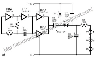
THE high forward voltage of l.e.d.s is a challenge for efficient battery use. In the circuit shown in Fig.1a, a 74HC14 inverter is used to “double” the voltage of a 6V rechargeable ex-mobile-phone battery and drive a string of three 5mm l.e.d.s. The oscillator around IC1a and IC1b generates a square wave at about 2·8kHz, and its output is buffered by IC1c and IC1d used in parallel to maximise current to the doubler.
LED Torch

Tuesday, May 15, 2012

PROGRAMMABLE TIMER FOR APPLIANCES

This programmable timer is usefu for domestic, commercial as well as industrial applications. It automatically turns the appliance on/off after a preset time. The time period can be varied from 8 seconds to 2 hours with the help of rotary switches S2 and S3. The circuit works in two modes: off mode and cyclic mode. Slide switch S4 is used for mode selection.

In the off mode, the appliance turns on after a preset time (set by rotary switch S2), remains on for another preset time (set by rotary switch S3) and then turns off. In the cyclic mode, this process repeats again and again.

The circuit is built around three quad two-input NAND gate ICs CD4011 (IC1, IC3 and IC5), two 14-bit binary ripple counters CD4020 (IC2 and IC4) and a relay driver transistor (T1). It works off a 12V DC, 500mA power supply. You can also power the circuit from mains by using a 12V DC, 500mA adaptor in place of the 12V DC power supply.
PROGRAMMABLE TIMER FOR APPLIANCES

Friday, May 11, 2012

Time Delay Touch Switch

Fitting switches which turn off automatically after a preset time in these locations can reduce the electricity consumed quite significantly. A single 100W bulb left burning all night (say eight hours) would consume 800W/hrs. The same bulb fitted with a switch which turned off automatically after say five minutes would consume only 83W/hrs, even in the unlikely event that it were to be activated ten times during this period.

Triac Control
There are two major problems to solve when designing a touch switch to replace a conventional mechanical light switch and these concern the power supply and noise immunity.

The main switching element used to control the light is a triac, a semiconductor a.c. switch. This is normally in its off or non-conducting state but can be switched into conduction by means of a small trigger current fed to its gate terminal. Once triggered it will remain conducting until the current through it drops below a certain value (known as the holding current). This occurs normally on a.c. supplies when the voltage drops to zero at the end of every mains half-cycle, and the triac must be retriggered again if the light is to remain on.

As with any switch, the voltage across a triac when it is in its off state will be the supply voltage (in this case 230V a.c.). When the triac is on, the voltage across it will be around 1V a.c., depending on the current. The triac therefore dissipates very little power so no heatsink is required.

Monday, May 7, 2012

MAINS Failure Alarm

MAINS failure alarms are often employed in situations where the removal of the mains supply from a piece of equipment can have adverse or even disastrous consequences.

Very often, the “failure” may simply be the result of the switch on the outlet socket being operated inadvertently and this may have no immediately noticeable effect on the equipment. The results of the mistake may only become evident a few hours or even days later, when it is too late.

The circuit described here overcomes all of these problems at a stroke and also does away with the need for mains plugs, or indeed any connections to the mains at all. It does so by monitoring the electric field which exists around a cable connected to the a.c. supply (whether it is carrying a current or not).

By placing it on or near to the cable of the appliance to be monitored, it will also sound the alarm if the fuse in the plug blows, the outlet is switched off or the plug disconnected. It will only fail to detect the situation where the equipment itself has been switched off via its own built-in switch. However, since many appliances such as freezers do not have on/off switches, this is not really a problem.

The circuit is extremely simple and inexpensive to build. Its simplicity and lack of any specialized components should make it attractive to many constructors who will probably already have most of the components to hand. The absence of any mains connections should make it an ideal project for a beginner.
mains failure alarm schematic
As with many simple circuits, however, the advantages and possible uses take longer to describe than the operation of the circuit diagram which is shown in Fig.1.

Friday, May 4, 2012

Voltage Booster – High Voltage from a 5V Supply

Digital circuits operating from 5V regulated supplies are common but occasionally a higher voltage is required, perhaps for a bio-medical circuit, or for liquid level measurement or for monitoring high resistance contacts. For such circuits a means of generating a high voltage from the 5V supply can be a solution. Diode/capacitor multipliers can offer advantages over switched-mode circuits, since they do not use inductors, are easier to design and troubleshoot and often generate less radiated interference.

The principle of the voltage multiplier is fairly well known. A capacitor is used with a square wave drive signal to “pump” current through a pair of diodes, roughly doubling the supply voltage. A series of such stages can be cascaded to raise the voltage in multiples of the supply, but it is possible to improve efficiency and reduce the number of stages by using two driving signals with opposite phases. However, each diode incurs a drop of about 0.6V so with two diodes per stage, and with an initial supply of just 5V this becomes significant, leading to poor efficiency and an impractical number of stages.
Voltage Booster
These problems are overcome in the Voltage Booster circuit design of Fig.1 by increasing the voltage before multiplication with IC1, an SI7660 “negative rail generator” (not the ICL7660 – ARW). The additional negative supply is generated very efficiently since switching is performed not by diodes but by CMOS switches in the IC, which cause almost no voltage loss at low currents.

Friday, April 27, 2012

PIC Based Air Quality Monitor

Idealy if you have a combustion heater in your home, there should be some means of monitoring the air quality. This is where the Air Quality Monitor comes in, it measures both carbon dioxide and carbon monoxide levels, and displays the results on LED bargraphs. If the concentration of either of these gases rises above a preset level, a loud alarm will sound, which means that you should turn off the heater and open the room up to fresh air.

Each bargraph comprises eight LEDs that light invidually to show eight distinct levels. In between values are displaed by lighting two adjacent LEDs. This gives a total of 15 levels that can be displayed. The four lower LEDs are green, followed by two orange and then two red LEDs. An automatic dimming circuit ensures that the LED displays are not too bright at night.

In addition, the alarm sounds if any of the top three LEDs light in either display. There are three alarm levels:
  1. Main alarm sounds if the top LED lights. This consists of a 64ms-long 4kHz tone that repeats every 0.5s. 
  2. Less urgent alarm sounds if the second top LED is lit (top LED off). This alarm gives a 32ms-long 4kHz ‘chip’ every four seconds (4s). 
  3.   Warning alarm sounds if the third top LED is alight. This alarm mode gives a brief 16ms 4kHz ‘chirp’ every 16 seconds (16s). 
An internal fan at one end draws air through the box so that the internally mounted CO and CO2 sensors are presented with a continuous sample of the air that’s being monitored. Power for the unit comes from a 12V DC 500mA plugpack.

Monday, April 23, 2012

12V 10A High current Power Supply with battery backup

The full circuit diagram of the 12V 10A Power Supply is shown in Fig.1.Power of about 18V to 25V is applied to screw terminals pins 1 (+V) and 2 (–V).Although the power supply was originally designed to run packet radio transceivers, the unit is not just confined to this type of radio. In fact, any radio can be used with this power supply. It can also be used as a main source of power; ie the battery, or used as a standby source of power in the event of a power failure. There would be a float charge for the battery when mains voltage is applied, and the battery can be relied on to supply current to equipment when the mains supply fails.

The input current to the circuit is limited by a 5A fuse (FS1) for protection purposes. Relay RLA is a small ‘homemade’ reed type that is set to close the contacts when the current drawn through this relay coil is in the order of about 1.5A. When this occurs, RLA’s contacts close, current is drawn through resistor R1, LED1, R2 and onto R3. The voltage across resistor R3 is sufficient to turn on FET TR2, which supplies power to a 12V cooling fan.
12V 10A High current Power Supply with battery backup schematic

Tuesday, March 13, 2012

Universal Remote Control Receiver

The circuit diagram shown in Fig.1 uses a PNA4602M IR detector to receive an IR signal from  the remote control. It’s a neat device, which contains an IR receiver, amplifier and demodulator together in a single 3-pin package, and it’s normally used in circuits where you want to decode an IR remote control signal. 

The way the circuit (Fig.1) works is as follows. When there is no IR coded signal present, the output pin of IC1 remains high. This high signal is fed to the trigger input of the 555 timer (IC2), which being configured as a monostable timer, prevents the timer operating. 

Whenever you briefly press any key on the old remote control its IR signal is received by IC1 and output pin 1 produces a train of fast moving high and low pulses, which mimic the IR signal code sent by the remote control. We are not interested in this code, but as soon as the signal switches low it triggers the monostable timer IC2 and its output pin 3 goes high for a short period of time, set by resistor R2 and capacitor C2.

Sunday, March 4, 2012

LDR Based Water Pump Controller

Here is a simple solution for automatic pumping of water to the overhead tank. Unlike other water-level indicators, it does not use probes to detect the water level and hence there is no probe corrosion problem. It has no direct contact with water, so the chance of accidental leakage of electricity to the water tank is also eliminated.

sensor assembly
Two important advantages of the circuit are that the water level never goes below a particular level and no modification in the water tank is required. Fig. 1 shows the circuit of the water pump controller. The circuit uses an LDR-white LEDs assembly to sense the water level. It forms a triggering switch to energise the relay for controlling the pump. The LDR-LEDs assembly (shown in Fig. 2) is fixed on the inner side of the cap of the water tank without making contact with water. The light reflected from the water tank is used to control the resistance of LDR1.

Thursday, February 23, 2012

Portable Lamp Flasher


Here is a portable, high-power incandescent electric lamp flasher. It is basically a dual flasher (alternating blinker) that can handle two separate 230V AC loads (bulbs L1 and L2).

The circuit is fully transistorized and battery-powered. The free-running oscillator circuit is realized using two low-power, low-noise transistors T1 and T2. One of the two transistors is always conducting, while the other is blocking. Due to regular charging and discharging of capacitors C1 and C2, the two transistors alternate between conduction and non-conduction
states.

The collector of transistor T1 is connected to the base of driver transistor T4 through current-limiting resistor R5. Similarly, the collector of transistor T2 is connected to the base of driver transistor T3 through limiting resistor R6. These transistors are used to trigger Triac1 and
Triac2 (each BT136) through optotriacs IC1 and IC2, respectively, and switch on the power supply to external loads L1 and L2. IC1 and IC2 operate alternatively at a low frequency
determined by the values of capacitors C1 and C2.

Sunday, February 19, 2012

Long-Range IR Transmitter

Most of the IR remotes work reliably within a range of 5 metres. The circuit complexity increases if you design the IR transmitter for reliable operation over a longer range, say, 10 metres. To double the range from 5 metres to 10 metres, you need to increase the transmitted power four times.

If you wish to realise a highly directional IR beam (very narrow beam), you can suitably use an IR laser pointer as the IR signal source. The laser pointer is readily available in the market. However, with a very narrow beam from the laser pointer, you have to take extra care, lest a small jerk to the gadget may change the beam orientation and cause loss of contact.

Thursday, February 16, 2012

Three Phase Appliance Protector

Many of our costly appliances require three-phase AC supply for operation. Failure of any of the phases makes the appliance prone to erratic functioning and may even lead to failure. Hence it is of paramount importance to monitor the availability of the three-phase supply and switch off the appliance in the event of failure of one or two phases. The power to the appliance should resume with the availability of all phases of the supply with certain time delay in order to avoid surges and momentary fluctuations.

The complete circuit of a threephase appliance protector is described here. It requires three-phase supply, three 12V relays and a timer IC NE555 along with 230V coil contactor having four poles.